


The LM339 Comparator
- fezec

- Mar 2, 2019
- 4 min read
Updated: Mar 3, 2019
Today I’m discussing the LM339 Comparator. As the name implies, the LM339 compares which voltage, among two input voltages is greater. Furthermore, the operation outputs the result continuously in the form of an open-collector. The benefit of the LM339 is one that can monitor for drops or surges in voltage against a fixed reference. This is useful when a circuit needs to monitor voltage conditions. Such an IC enables a circuit or operator to take corrective action. A real world example that comes to mind is the raspberry pi 3’s ‘under voltage detected’ warning. The warning alerts the user that the board is not sufficiently powered. An undervoltage pi can result in decreased performance and or data loss. Another example could be found in backup batteries. Appliances that are necessary to perform properly despite power deficiencies make use of backup sources of power. A comparator is used to ensure that when a deficiency occurs in the main Vcc, a secondary powersource would kick in.
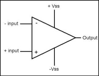
The above image illustrates the pins of a comparator circuit. At its most basic hookup, a comparator requires power, ground, a voltage to monitor and a reference voltage for comparison. I can only speculate at this point in time that the + and – noted alongside the inputs are used indicate the desired condition against the reference voltage. The proper nomenclature for the – and + inputs are the inverting (-) and non-inverting (+) inputs.

The LM339 is a Quad-channel Comparator, which allow up to 4 pairs of inverting and non-inverting inputs. Additionally, each channel also possesses output that will continuously reflect the comparison.

In the image above, I leverage channel 2 of LM339 as indicated by the component diagram. Channel 2’s output exists on pin 1, the inverting voltage on pin 6 and the non-inverting voltage on pin 7. Of course I’m also using pins 3 and 12 to provide Ground and Power to the IC itself. The circuit is currently set up on my workbench and connected to an oscilloscope so that I am able witness the voltages input to the comparator. To visualize the state of the output, I've incorporated 2 LEDs. When the circuit is closed, the red LED is lit. However, when the circuit is open the blue LED remains lit. In other words, if the non-inverting voltage is greater than that of the inverting voltage, the circuit remains open. When the non-inverting voltage is lower than that of the inverting voltage, the circuit is closed.
It should be made clear that the output of the LM339 comparator is an open-collector. What this means in layman terms, is that the output by default doesn't differ between HIGH and LOW. Instead it will sink current if the compared condition is met. As long as the condition is not met-the circuit remains open. To be honest, I initially struggled with this-Mostly, as I had expected a HIGH or LOW signal to be output as indicated by the literature on the LM339. Yet this wasn't the case. If you wish to obtain a HIGH or LOW signal, you must incorporate a pull-up resistor to an output supply. The LM339 can accept from 0 - 36V. When the circuit becomes active, there will be a path between Vcc and Ground.
Turning on the power to the breadboard, closes the circuit as indicated by the red LED. Referencing the voltages sampled by the Oscilloscope reveals why. The non-inverting (Shown in Yellow) voltage is lower than that of the inverting voltage (Shown in Pink).

The yellow line, which represents our non-inverting voltage appears fixed at 3.5V, while the inverting voltage or pink line remains steadily at 5V. I chose 3.5V as the non-inverting value because one caveats of the LM339 is that in order for the IC to work correctly, one of the inputs (either the inverting or the non-inverting) must be at least 1.5V below source voltage. Being that I am using 5 volts to power the circuit, I am required to cap one of the inputs to 5V-1.5V or 3.5V.
To achieve an upward limit of 3.5V, I devised a voltage divider using a 270 ohm and 680 ohm resistor. The resulting 3.5V is then fed into the comparator as the non-inverting voltage. Since only 1 input must remain capped, I chose to connect the inverting input directly to the power rail.
In order to further interact with this experiment, both inputs front load a trim potentiometer. This affords me the ability to simulate voltage rises and voltage decreases. At the moment each potentiometers' resistance is set at 0 ohms defaulting the values to their aforementioned max voltages. By increasing/decreasing the resistance of either potentiometer we can decrease/increase the applied potential respectively.
As I adjust the resistance of the inverting voltage, the purple line begins to dip towards the yellow (non-inverting voltage) as seen in the video below. The moment at which the inverting voltage equals the non-inverting voltage, the output's path to ground becomes disconnected thus completing the blue LED circuit. Only once I increase the potential above 3.5Volts is the Path to Ground once again available.
As you would expect, increasing the resistance of the potentiometer connected to our non-inverting voltage, reduces our voltage from its 3.5 volts. Thus creating a new baseline for which our inverting voltage is compared.
It should be made known that it's possible for the voltages to fluctuate causing the output to oscillate between states. For some projects this may not be desired and for some it may be dire. In the above video, at the 2:33 timestamp, you can witness such an oscillation between state as indicated by the brief oscillation between the LEDs. This occurs because the slightest change in voltage raises and lowers the inverting voltage around our fixed 3.5V reference. In the next writeup, we will take a look at how we can overcome this using feedback.


Comments